

Last fall I helped a local school district install a Cisco wireless network consisting of 1142n APs and a 5508 controller. All was working well until recently when one of their techs received the district's first AppleTV.
Of course my first question was what VLAN(s) the AppleTV and the iOS device were connected. That was the first problem which was easily fixed by placing them on the same VLAN. The next problem is how Apple's devices find other devices on the same layer 2 network. Apple uses Multicast DNS (mDNS), which they call Bonjour, to locate devices. Every device on a subnet advertises its capabilities to the multicast address 224.0.0.251. By default these advertisements are set to have a Time To Live (TTL) of 1 which prevents them from crossing routed boundaries even if multicast routing is configured on the network.
It was easy enough to put the AppleTV onto the same wireless VLAN as the user devices so we didn't have to come up with a solution for that. To get the two devices talking is actually quite simple. By default Cisco WLCs have multicast disabled. This of course prevents Bonjour's discovery process from functioning. Enabling multicast is done under the Controller tab of the WLC web page. There are three options, disabled, unicast and multicast.
You might wonder how you can have unicast multicast, but it's not a contradiction in terms. Because of the way traffic is tunneled from the APs to the controller, the multicast traffic is actually sent to the APs using CAPWAP unicast packets. If you switch to multicast multicast mode and the switches are properly configured, the CAPWAP packets containing the wireless multicast traffic is only sent to APs that have joined the multicast CAPWAP group. In a larger environment this can cut down on the amount of traffic sent as well as eliminate traffic going to APs that don't need the packets.
Most of the major networking vendors have released or are planning to release solutions to the problems Bonjour faces in the enterprise network. In addition there have been petitions online to Apple for them to make their products work better in enterprise networks. Hopefully soon these challenges will be a thing of the past and Apple products will "just work" at home and in the office.
Subscribe To
Showing posts with label configuration. Show all posts
Showing posts with label configuration. Show all posts
Tuesday, August 14, 2012
Friday, March 30, 2012
Backup Your VLAN Database
A junior admin at XYZ corporation was tasked with adding a switch to the XYZ network. He grabbed a spare switch out of stock that had been previously used. After he plugged in the switch, most users were complaining that they couldn't connect to company resources over the network. Your manager has tasked you with determining the cause of the problems and fixing them.
Sounds like a test question doesn't it? Well unfortunately it happens often enough in real production networks. A new switch is added with VTP server mode turned on and a higher revision number than the current VLAN database. This can cause a totally bogus VLAN database to be propagated to the network via VTP if it is enabled on the production switches. While there are plenty of ways to prevent this from happening, even the best network team can occasionally have a bad day.
Cisco's EEM provides a handy way of backing up your vlan.dat file so that you can quickly and relatively easily restore your VLAN database.
event manager session cli username "user" ! Determines the user that the script runs as.  If you use TACACS+ command authentication this is important.
event manager applet backup-vlan
 event timer cron cron-entry "0 23 * * *" maxrun 60000 ! Schedules the script to run at 23:00 every day.
 action 1 cli command "enable"
 action 2 cli command "configure terminal"
 action 3 cli command "file prompt quiet" ! Eliminates the "Are you sure?" prompts.
 action 4 cli command "end"
 action 5 cli command "copy const_nvram:/vlan.dat scp://user:password@FQDN/vlan.dat" ! Copies vlan.dat to a SCP server.
 action 6 cli command "configure terminal"
 action 7 cli command "no file prompt quiet" ! Restores the "Are you sure?" prompts.
 action 8 cli command "end"
Sunday, March 11, 2012
Automatic Recovery for Err-disabled Interfaces
There are four primary states for interfaces on Cisco switches: up, down, administratively disabled and err-disabled. Up and down are fairly self explanatory. Administratively disabled means that the port is configured to be shutdown by the administrator using the CLI. Err-disabled though can be a bit baffling to a new network engineer.
The err-disabled interface state can be caused by many situations including:
In some cases, it would be safe to allow the switch to auto recover the interface to up if the condition that caused the err-disabled state has cleared. For this example, let's assume that a port-security violation caused the error (psecure-violation). This is a relatively benign error to auto recover because if the violation still exists, port security will rapidly trip again putting the interface back into err-disabled. The default is that the switch will clear the state after 5 minutes. So to have the switch auto recover the interface the following configuration would need to be added.
The err-disabled interface state can be caused by many situations including:
- Bad cabling
- Duplex mismatch
- BPDU guard violation
- Port-Security violation
- Link-flap detection
The complete list is on Cisco's site.
An engineer can recover an interface by entering configuration mode for the interface and issuing the shutdown and then no shutdown commands. By default the interface will remain err-disabled until a human intervenes because auto recovery is disabled as is shown by the following show command.
SWITCH#show errdisable recovery
ErrDisable Reason            Timer Status
-----------------            --------------
arp-inspection               Disabled
bpduguard                    Disabled
channel-misconfig (STP)      Disabled
dhcp-rate-limit              Disabled
dtp-flap                     Disabled
gbic-invalid                 Disabled
inline-power                 Disabled
l2ptguard                    Disabled
link-flap                    Disabled
mac-limit                    Disabled
loopback                     Disabled
pagp-flap                    Disabled
port-mode-failure            Disabled
pppoe-ia-rate-limit          Disabled
psecure-violation            Disabled
security-violation           Disabled
sfp-config-mismatch          Disabled
small-frame                  Disabled
storm-control                Disabled
udld                         Disabled
vmps                         Disabled

Timer interval: 300 seconds

Interfaces that will be enabled at the next timeout:
In some cases, it would be safe to allow the switch to auto recover the interface to up if the condition that caused the err-disabled state has cleared. For this example, let's assume that a port-security violation caused the error (psecure-violation). This is a relatively benign error to auto recover because if the violation still exists, port security will rapidly trip again putting the interface back into err-disabled. The default is that the switch will clear the state after 5 minutes. So to have the switch auto recover the interface the following configuration would need to be added.
Similar commands can be entered for the other reasons listed above in the show command or you can set all reasons to recover by using the keyword all. Be careful where you enable the auto recovery, it might not be your friend on all switches. For example, you wouldn't want a link on a core switch having a problem to start flapping because of auto recovery causing a network convergence every 5 minutes (or whatever you set the timer to).SWITCH# configure terminal SWITCH(conf)#errdisable recovery interval 300 ! Default setting shown for completeness. SWITCH(conf)#errdisable recovery cause psecure-violation SWITCH(conf)#end SWITCH#copy running-config startup-config
Tuesday, March 6, 2012
No Port for You! Using Cisco Port Security
Most Cisco switches support a feature known as Port Security. Port security gives the network engineer the ability to have more granular control as to what device(s) can be plugged into a switch port. There are a couple of usual use cases for Port Security.
Uses for Port Security
The first use case is to block unauthorized hubs, switches or access points from being used on the network. In this scenario, Port Security is configured to allow a set number of MAC addresses to come from a certain port. In most cases it would be set to two, one for the PC and one for the IP phone. Any MAC addresses past the first two seen would either be denied access to the network or cause the port to be err-disabled (more on the violation modes later). The allowed MAC addresses can either be statically assigned, dynamically learned, or dynamically learned and made permanent.
The other use case is to ensure that a secure piece of equipment like a credit card reader or biomedical device is the only device able to use the port. In this case, the port is usually setup for a static MAC address. Any other hosts are subject to the configured violation mode setup on the port. If needed, more than one MAC address can be statically assigned to a single port.
Configuring Port Security
Now let's take a look at how Port Security is configured on a switch port.
Aging MAC Addresses
Another twist on dynamically learned MAC addresses is to use aging to limit the number of devices on a port, but not necessarily restrict devices based on the MAC address. In this configuration the port is set to limit the number of MAC addresses allowed, but as MAC addresses are no longer seen for a set type they are aged out allowing new MAC addresses to be added to the port without a violation. The aging can either be absolute or based on inactivity.
Wrap Up
While Port Security is a very powerful tool, I have not seen it as widely deployed as one would think. I think part of that is lack of awareness and the other part is fear of taking down a production port automatically. With the right planning and knowledge, both can be overcome. I really suggest people consider adding Port Security to their port activation templates. Even if it is just to stop unauthorized hubs, switches and access points, there is definite benefit.
Uses for Port Security
The first use case is to block unauthorized hubs, switches or access points from being used on the network. In this scenario, Port Security is configured to allow a set number of MAC addresses to come from a certain port. In most cases it would be set to two, one for the PC and one for the IP phone. Any MAC addresses past the first two seen would either be denied access to the network or cause the port to be err-disabled (more on the violation modes later). The allowed MAC addresses can either be statically assigned, dynamically learned, or dynamically learned and made permanent.
The other use case is to ensure that a secure piece of equipment like a credit card reader or biomedical device is the only device able to use the port. In this case, the port is usually setup for a static MAC address. Any other hosts are subject to the configured violation mode setup on the port. If needed, more than one MAC address can be statically assigned to a single port.
Configuring Port Security
Now let's take a look at how Port Security is configured on a switch port.
The first command after entering interface configuration turns Port Security on for the port. Next, the MAC address to be allowed is configured. Finally the last line sets the violation mode to protect. There are three modes: protect, restrict and shutdown.
SWITCH(config)# int Gi3/0/27
SWITCH(config-if)#switchport port-security
SWITCH(config-if)#switchport port-security mac-address 0000.aaaa.bbbb
SWITCH(config-if)#switchport port-security violation restrict
- Protect - When a violation of the Port Security rules is detected, the port will drop all traffic to the violating MAC addresses and note the violation in the logs. The port also stops learning MAC addresses even if the violation is only for a VLAN. As such Cisco does not recommend this mode.
- Restrict - When a violation of the Port Security rules is detected, the port will drop all traffic to the violating MAC address, note the violation in the logs, and send an SNMP trap. This is the recommended mode from Cisco versus Protect.
- Shutdown - When a violation of the Port Security rules is detected, the port is put into err-disabled state until either the engineer clears the port or the timer expires if errdiable recovery is configured.
Sticky MAC Addresses
This example is very similar to the first, but you will notice that instead of a MAC address, the keyword sticky is substituted. This configures the port such that the first MAC address it learns will become the secure MAC address for the port until changed by the network engineer. All other MAC addresses learned will be considered in violation. There is an implied default configuration of "switchport port-security maximum 1" in this configuration that limits the port to one mac address learned. If you wanted to let the port have more than one sticky MAC address, enter the command "switchport port-security maximum <number>".
SWITCH(config)# int Gi3/0/27
SWITCH(config-if)#switchport port-security
SWITCH(config-if)#switchport port-security mac-address sticky
SWITCH(config-if)#switchport port-security violation restrict
Aging MAC Addresses
Another twist on dynamically learned MAC addresses is to use aging to limit the number of devices on a port, but not necessarily restrict devices based on the MAC address. In this configuration the port is set to limit the number of MAC addresses allowed, but as MAC addresses are no longer seen for a set type they are aged out allowing new MAC addresses to be added to the port without a violation. The aging can either be absolute or based on inactivity.
In the above example, the port is set to age out a MAC address after 480 minutes go by regardless of activity.
SWITCH(config)# int Gi3/0/27
SWITCH(config-if)#switchport port-security
SWITCH(config-if)#switchport port-security aging time 480 type absolute
SWITCH(config-if)#switchport port-security violation restrict
This example shows the configuration to have the MAC address aged out 10 minutes after the last activity.
SWITCH(config)# int Gi3/0/27
SWITCH(config-if)#switchport port-security
SWITCH(config-if)#switchport port-security aging time 10 type inactivity
SWITCH(config-if)#switchport port-security violation restrict
Wrap Up
While Port Security is a very powerful tool, I have not seen it as widely deployed as one would think. I think part of that is lack of awareness and the other part is fear of taking down a production port automatically. With the right planning and knowledge, both can be overcome. I really suggest people consider adding Port Security to their port activation templates. Even if it is just to stop unauthorized hubs, switches and access points, there is definite benefit.
Tuesday, October 18, 2011
NMIS Configuration Part 2
 |
| Configuration>System>Nodes |
This will bring up the Nodes listing showing currently configured nodes. To add a node, click on add to the right of Action on the top right part of the screen.

Once you click Add, you will see the add node screen as shown below. There are a lot of variables to configure for each node.
- Name: This is the name of the node and should have no spaces in it. This must be unique.
- Name/IP Address: This is the IP or the FQDN of the node.
- Group: This is the group in which the node will be displayed.
- Select Model: This is the data model that NMIS will use to gather SNMP data from the device. In most cases automatic works best.
- Active: This defines whether the node is currently actively polled. You can use this set to false to take a group of nodes out of active monitoring without deleting them.
- Ping: Should NMIS ping the node for availability?
- Collect: Should NMIS collect SNMP data from the node?
- CBQoS: Should NMIS collect data about Class Based QoS on inbound, outbound, both or none?
- Modem Calls: Should NMIS collect data on modem calls (not used often)?
- Threshold: Should NMIS run threshold calculations on this node?
- Rancid: Should the Rancid add in add this node to a rancid configuration file? (I'm not sure if this tool is still supported.)
- Web Server: Does this device run a webserver?
- Net Type: Is this device WAN or LAN?
- Role Type: Is the device core, distribution or access?
- Depend: What devices must be up for this device to be up? This provides NMIS with a way of knowing when not to alert on a node if an upstream node is down.
- Services: Should NMIS check to make sure certain services are running on the node?
- Time Zone: What is the time zone offset for the device from GMT?
- SNMP Settubgs: What version of SNMP should be used to poll the device and what is the configuration for that version?

Once the nodes are added, it may take 10-15 minutes for data to start to show up depending on how often the NMIS cron jobs are set to run. This concludes the basic configuration of NMIS. There are a lot more nerd nobs in the software, but unfortunately good documentation is not available for the product, especially the newest 8.x versions. Opmantek has said that documentation is a focus for their team so hopefully it will be coming soon. In my next post I will discuss how to use NMIS once it is collecting data.
Monday, October 17, 2011
NMIS Configuration Part 1
Since I posted my first article about NMIS, I have had several requests to do a series on how to configure NMIS. Although I took a break from blogging in September, here is the first in the requested series.
NMIS' configuration is stored in text files in /usr/local/nmis8/conf/ and can be edited by hand. However, it is highly recommended to use the built in tools to edit the configuration. The main configuration can be found under Configuration > System > NMIS Configuration.
NMIS' configuration is stored in text files in /usr/local/nmis8/conf/ and can be edited by hand. However, it is highly recommended to use the built in tools to edit the configuration. The main configuration can be found under Configuration > System > NMIS Configuration.
Monday, August 29, 2011
Cisco Nexus 1000v Roundup
This post is merely an index for the 6 post series I did on the Cisco Nexus 1000v. I hope that beyond being a good learning experience for myself that it will benefit others.
Cisco Nexus 1000v - Adding Physical Ports (Part 6)
The previous posts have established a fully configured, but unused Nexus 1000v. At this point it's like having a physical switch in the rack, powered up and configured, but with no network cables attached. In VMWare, the "cables" are attached using the vSphere Client.
Attaching Physical Ports to the Nexus 1000v
Attaching Physical Ports to the Nexus 1000v
- Connect to vCenter using the vSphere Client
- Go to Networking Inventory and select the Nexus distributed virtual switch (dVS).
- Right click on the Nexus and choose add host.
- Select the host and vmnic(s) to use and change their DVUplink port group to system-uplink (or what you named the system uplinks in your port group on the Nexus) for the system uplink ports and vm-uplink for the VM networking ports.
- Click next and choose not to migrate the vmk0 or VMs. (I prefer to verify the Nexus 1000v's operation before migrating anything.)
- Click Finish.
- Repeat for all hosts in the cluster.
Migrating vmk0 Interfaces to Nexus
Once you have added a few test VMs to the Nexus and are certain that the Nexus 1000v is working properly, it's time to migrate the last physical NIC from the vSwitch to the Nexus 1000v and with it the vmk0 interface used for vMotion and VMWare host management. Keep in mind that if you don't need this NIC for bandwidth reasons, it is not mandatory to move these services to the Nexus 1000v.
- Connect to vCenter using the vSphere Client.
- Go to Networking Inventory and select the Nexus dVS.
- Right click on the Nexus and choose manage host.
- Select the hosts and click next twice.
- Click on the destination port group for the vmnic used by vmk0 and choose the Nexus port group.
- Click next and then finish without migrating VMs.
You will need to repeat this for each host in the cluster. Leave the host with the active VSM for last and make sure to migrate it's NICs to the Nexus before disconnecting the vSwitch from the vmnic.
Friday, August 26, 2011
Cisco Nexus 1000v Software Installation (Part 5)
In this article I will run through installing the Virtual Ethernet Module (VEM) and creating the initial port groups on the Nexus 1000v.
Installing the Virtual Ethernet Module (VEM)
- Open the vSphere client and connect to vCenter.
- Right click on the host that you are going to install the VEM on and choose Maintenance Mode. (NOTE: This will vMotion all guests from that host to other hosts if you have vMotion enabled, otherwise those guests will be shutdown.)
- Copy the VEM bundle from the Nexus 1000v install zip file to the vMA or to the computer that you are running vCLI on.
- Use the vCLI to install the VEM with the following command: vihostupdate -install -bundle <path to VEM Bundle> --server <host IP>
As you can see, installing the VEM software is fairly simple.
Creating the Port Groups on the Nexus 1000v
The Nexus 1000v uses port-profile configurations to define the configuration for each type of interface. In this part of the install we need to setup profiles for the physical NICs that will uplink to the hardware switch infrastructure for both the system VLANs like VMK0 and the Nexus Control traffic as well as the VM uplinks for normal guest VLAN traffic. On the Nexus 1000v, physical NICs are all of type Ethernet and virtual NICs are vEthernet.
- Connect to the switch management IP address using SSH.
- Type config t and enter to enter configuration mode.
- Configure a port profile to use for your system uplink ports (VMK0, Nexus Control, Nexus Packet, Nexus Management). Below is an example:
port-profile type ethernet vm-uplink vmware port-group switchport mode trunk ! In my lab, 255 is MGMT, 256 is Nexus Packet and Control and 101 is for VMK0 switchport trunk allowed vlan 101, 255-256 switchport trunk native vlan 255 ! This command has Nexus create port-channels automatically channel-group auto mode on no shutdown ! System VLANs come up before the VSM is fully initialized system vlan 101,255-256 description SYSTEM-UPLINK state enabled - Configure a port profile to use for the VM Guest networks.
port-profile type ethernet vm-uplink
  vmware port-group
  switchport mode trunk
  switchport trunk allowed vlan 2,102,104-105,259
  switchport trunk native vlan 102
! This command has Nexus create port-channels automatically
  channel-group auto mode on
  no shutdown
! System VLANs come up before the VSM is fully initialized.
  system vlan 102
  description VM-UPLINK
  state enabled
- Configure port profiles for the guest networking to match the old vSwitch port-groups.
port-profile type vethernet example-vlan vmware port-group example-vlan switchport access vlan
switchport mode access no shutdown state enabled - Save the new configuration by doing copy running-config startup-config
Now that we have everything configured, the next post will be how to plug the network into the Nexus 1000v.
Cisco Nexus 1000v Software Installation (Part 4)
In the last post, I configured the VMWare stock vSwitch to allow us to start the Nexus 1000v install. I forgot to mention one thing that I usually do (it's not required) to help with mapping physical ports. The VMWare vSwitch supports CDP, but is usually set to listen only. To change it so that it will send out CDP packets you need to do the following:

- Using the VMWare vCLI either from a desktop of the vMA appliance run the following command: vicfg-vswitch -server <servername> -B both vSwitch0
- Repeate for all of the ESX Hosts in the cluser.
The next step in the Nexus 1000v installation is to install the Virtual Supervisor Module (VSM) VM appliance(s).
Deploying the Virtual Supervisor Module (VSM)

- Download and decompress the Nexus 1000v software from Cisco.
- Open up the vSphere Client and connect to vCenter.
- Go to File and then Deploy OVF Template.
- Select the OVF file under the Nexus 1000v VSM install folder.
- Accept the details and the EULA.
- Give the VSM a name and choose next.
- Choose the ESX data store for the VSM and choose next.
- Choose thick provisioned and click next. (NOTE: Thin provisioning is not supported by Cisco for the VSM.)
- Map the virtual NICs to the appropriate port groups on the vSwitch.
- Power up the VSM and connect to its console using vSphere client.
- Once booted, go through the text based administrative setup to configure the following:
- Administrative user password
- Role (Standalone/primary/standby) The first VSM will be primary unless it is to be the only VSM and then it would be standalone.
- Domain ID. This number serves to tie VSMs to a VEM and to vCenter. Each Nexus 1000v instance must have a unique domain ID.
- Continue with the basic system configuration including:
- SNMP Read-Only community string
- Naming the switch
- Assigning the management IP address settings
- Enabling or disabling services. NOTE: Make sure http and ssh are enabled as they are used later in the process.
- Open up a web browser to http://<nexus1000vIPaddress/ and click on "Launch Installer Application" (Requires Java Web Start and doesn't seem to currently work with Chrome).
- Give the wizard the credentials for the VSM that you created earlier.
- Give the wizard the credentials for accessing vCenter and the vCenter IP Address.
- Select the cluster where the VSM is installed.
- Assign the proper VLANs to the VSM's virtual NICs by choosing advanced L2 and then chose the proper port groups.
- Configure settings for the VSM.
- Review the configuration.
- Tell the wizard not to migrate any hosts or VMs and let it finish. It will reboot the VSM multiple times before reporting that it is done.


Friday, August 19, 2011
Cisco Nexus 1000v Software Installation (Part 3)
In this article I will examine the process of configuring the default VMWare vSwitch with the VLANs needed to start the Nexus 1000v Install.
The first steps to getting a Nexus 1000v installed are actually to get the basic VMWare vSwitch configured and operating.
Assumptions:
· ESX is already installed
· vCenter VM is already installed and configured
· vSphere Client is installed on workstation
· VLANs for Nexus Packet and Capture interfaces (can be the same VLAN) are created on the network.
· VLAN for Nexus Management interface is created on the network.
· The ESXi hosts have their ports configured as trunks with the Nexus Packet, Capture and Management VLANs allowed as well as the VLAN used for the ESX hosts’ IP addresses (VMK0).
Configuring ESXi vSwitch
- Open vSphere Client and connect to vCenter.
- Click on the host to configure.
- Click on the configuration tab.
- Click on networking.
- Click on properties.
- Click on add.
- Click on Virtual Machine and then Next

- Give the network a label and a VLAN ID (0 indicates the native vlan). NOTE: This label must be consistent on all hosts for vMotion.


Monday, June 6, 2011
Configuration Rollback Update
Jeff over at www.fryguy.net has just blogged about the Cisco Archive and Configure tools that I discussed back in March. He does a good job of explaining how to use it to avoid long downtimes for a mistyped command.
Friday, May 6, 2011
Fun with Port-Channels
This week I did what I've done hundreds of times before. I configured a new port-channel on a Cisco switch for a server. In doing so I ended up with two new scenarios that I had never seen before.
The first issue was more of a head scratcher than a production problem, but nonetheless it caused me to stop and wonder why.
My second issue was that a server connected to a port-channel was disabling one of the NICs saying that it was faulted. Again defaulting the configurations and recreating the port-channel cleared up that issue.
The moral of my story is that even though your configuration may be 100% correct, you may have confused IOS so try starting over.
The first issue was more of a head scratcher than a production problem, but nonetheless it caused me to stop and wonder why.
PAHA-1A-6509E-SW1#show etherchannel 403 summary
Flags:  D - down        P - bundled in port-channel
        I - stand-alone s - suspended
        H - Hot-standby (LACP only)
        R - Layer3      S - Layer2
        U - in use      N - not in use, no aggregation
        f - failed to allocate aggregator

        M - not in use, no aggregation due to minimum links not met
        m - not in use, port not aggregated due to minimum links not met
        u - unsuitable for bundling
        d - default port

        w - waiting to be aggregated
Number of channel-groups in use: 34
Number of aggregators:           35

Group  Port-channel  Protocol    Ports
------+-------------+-----------+-----------------------------------------------
403    Po403(SD)       LACP
403    Po403A(SU)      LACP      Gi1/3/45(P)    Gi1/4/14(P)    Gi2/3/45(P)

Last applied Hash Distribution Algorithm: Fixed
My second issue was that a server connected to a port-channel was disabling one of the NICs saying that it was faulted. Again defaulting the configurations and recreating the port-channel cleared up that issue.
The moral of my story is that even though your configuration may be 100% correct, you may have confused IOS so try starting over.
Thursday, March 31, 2011
Using Cisco Wireless Lan Controllers for a Wired Guest Network
Most people are familiar with using Cisco's mobility anchors to provide a wireless guest network. The usual topology is that you have a controller with CAPWAP access points connected to it and then a foreign "anchor" controller that is located in the DMZ. Between the two controllers traffic is tunneled to logically separate the traffic from the rest of the regular network. In this way guest traffic can be effectively managed while keeping internal resources secure.
The same separation can be achieved for a wired guest LAN by using the same WLC architecture. Setting it up requires the following:
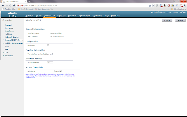
Login to the local WLC web GUI and go to Controller and then Interfaces and click New. This will bring you to the following screen where you give the Interface a name and tell it what VLAN it should be on.

Once the information is entered, click apply. This will bring you to another settings page for the new interface. In this screen you need to click the box marked Guest LAN and then click Apply.
Now go to WLAN and then click Go next to where it says Create New. This will bring you to the following screen where you will choose type Guest LAN and give the profile a name.

Clicking Apply will bring you to the WLANs Edit screen for the new profile. Here there are a few choices to be made about security. The default is that users will need to login using web authentication if they want onto this guest network. This requires that you have either setup local usernames and passwords, perhaps through the lobby ambassador setup, or have guest accounts through AAA. For this example I will use the Web Passthrough option with makes the user accept an acceptable use policy before gaining access. On the general tab I clicked enable and chose the guest-wired-lan interface that we created earlier as the Ingress Interface.

Next I clicked on the Security Tab and Layer 3 Tab to change the Layer 3 Security to Web Passthrough. Note that you also have the ability to require web passthrough users to give you their e-mail address, but it doesn't validate it is a real address.

Once you click Apply you will be back to the WLANs list page. On the right side of the page there is a blue box with a white down arrow next to the WLAN profile we created. Hover over it and choose Mobility Anchors. Once you're in that page you will choose the IP of the foreign anchor controller from the drop down and then click Mobility Anchor Create.

This completes the configuration of the local WLC.
Configure the Anchor Controller
Login to the anchor controller and click on WLANs and then Create a new WLAN profile just like the one on the Local Controller above except that the ingress interface is None and don't click enabled. Once you click apply, go to the mobility anchors for the new profile and make sure the Switch IP Address is set to (local) and click mobility anchor create. Once you have done this, you can go back to the profile screen and check enabled.
Wrap Up
This article is a rather whirlwind how to of setting up a guest wired network using the Cisco Wireless LAN Controllers. There are many intricacies not discussed here, but there are plenty of good documents on Cisco's website about how to configure the WLCs. I do have a question for anyone from Cisco or a wireless guru. If you have multiple WLCs on the local LAN, can you have the same wired guest vlan piped to all of them or do you have to have a different vlan for each controller? If you can have the same vlan, how does the traffic know which controller to associate with?
- The WLC inside the network must have it's interface setup as a dot1q trunk to handle multiple VLANs
- UDP Port 16666 or IP Protocol 97 must be able to pass through the firewall between the inside WLC and the anchor WLC.
- A dedicated L2 VLAN for the guest wired network
- Mobility Groups are already configured on the WLCs.
- DHCP configured on the Anchor Controller
Configure the Ports
First go to the switch connected to the local WLC and do the following assuming that the WLC is connected to Gi1/0/1 and the new guest wired vlan is 601
Next go to the switch connected to the access port(s) that you want on the guest wireless and do the following:
switch#configure t
switch(config)#interface Gi1/0/1
switch(config-if)# switchport trunk allowed vlan add 601
switch#configure t
switch(config)#interface range gi2/0/1 - 5
switch(config-if-range)# switchport access vlan 601Login to the local WLC web GUI and go to Controller and then Interfaces and click New. This will bring you to the following screen where you give the Interface a name and tell it what VLAN it should be on.

Once the information is entered, click apply. This will bring you to another settings page for the new interface. In this screen you need to click the box marked Guest LAN and then click Apply.

Now go to WLAN and then click Go next to where it says Create New. This will bring you to the following screen where you will choose type Guest LAN and give the profile a name.

Clicking Apply will bring you to the WLANs Edit screen for the new profile. Here there are a few choices to be made about security. The default is that users will need to login using web authentication if they want onto this guest network. This requires that you have either setup local usernames and passwords, perhaps through the lobby ambassador setup, or have guest accounts through AAA. For this example I will use the Web Passthrough option with makes the user accept an acceptable use policy before gaining access. On the general tab I clicked enable and chose the guest-wired-lan interface that we created earlier as the Ingress Interface.

Next I clicked on the Security Tab and Layer 3 Tab to change the Layer 3 Security to Web Passthrough. Note that you also have the ability to require web passthrough users to give you their e-mail address, but it doesn't validate it is a real address.

Once you click Apply you will be back to the WLANs list page. On the right side of the page there is a blue box with a white down arrow next to the WLAN profile we created. Hover over it and choose Mobility Anchors. Once you're in that page you will choose the IP of the foreign anchor controller from the drop down and then click Mobility Anchor Create.

This completes the configuration of the local WLC.
Configure the Anchor Controller
Login to the anchor controller and click on WLANs and then Create a new WLAN profile just like the one on the Local Controller above except that the ingress interface is None and don't click enabled. Once you click apply, go to the mobility anchors for the new profile and make sure the Switch IP Address is set to (local) and click mobility anchor create. Once you have done this, you can go back to the profile screen and check enabled.
Wrap Up
This article is a rather whirlwind how to of setting up a guest wired network using the Cisco Wireless LAN Controllers. There are many intricacies not discussed here, but there are plenty of good documents on Cisco's website about how to configure the WLCs. I do have a question for anyone from Cisco or a wireless guru. If you have multiple WLCs on the local LAN, can you have the same wired guest vlan piped to all of them or do you have to have a different vlan for each controller? If you can have the same vlan, how does the traffic know which controller to associate with?
Friday, March 25, 2011
Cisco Config Rollback and Replacement
In the previous two posts I have outlined how to create a configuration archive and how to compare configurations. In this post I will look at how to take an archived configuration and use it to replace the current configuration for rolling back changes. This article assumes that you already have a configuration archive in place.
Before making any changes to the configuration you need to run the command archive command to force IOS to make a backup copy of the current running-config. Once this is done, make any changes to the configuration. At this point you've either got a new running-config that you like and that works or you have created a problem and it's time to rollback through configuration replacement.
If you need to rollback the changes, you will need to do the following:
The configure revert now and configure confirm are both optional commands depending on how you configure the replace command and the outcome. For example if you are sure that you don't want to revert to the previous running-config typing configure confirm will make the change permanent and resets the timer set in the replace command. In the above example because we set the time 5 part of the command we must issue configure confirm within 5 minutes or IOS will automatically revert to the previous running config. If you find that you need to revert immediately to the previous config you run the configure revert now command.
As you can see, this can be good for making and rolling back changes as necessary. Theoretically you can also take a configuration file and edit it offline and then copy it back to the device with the changes. I say theoretically because you have to be very careful to meet the requirements of the IOS Configuration file in terms of indention.
Before making any changes to the configuration you need to run the command archive command to force IOS to make a backup copy of the current running-config. Once this is done, make any changes to the configuration. At this point you've either got a new running-config that you like and that works or you have created a problem and it's time to rollback through configuration replacement.
If you need to rollback the changes, you will need to do the following:
Router# configure replace scp://scpuser:scppasswd@scpserver/configuration1.cfg revert error  time 5
Router#configure revert now
Router#configure confirm
The configure revert now and configure confirm are both optional commands depending on how you configure the replace command and the outcome. For example if you are sure that you don't want to revert to the previous running-config typing configure confirm will make the change permanent and resets the timer set in the replace command. In the above example because we set the time 5 part of the command we must issue configure confirm within 5 minutes or IOS will automatically revert to the previous running config. If you find that you need to revert immediately to the previous config you run the configure revert now command.
As you can see, this can be good for making and rolling back changes as necessary. Theoretically you can also take a configuration file and edit it offline and then copy it back to the device with the changes. I say theoretically because you have to be very careful to meet the requirements of the IOS Configuration file in terms of indention.
Monday, March 21, 2011
Cisco Config Diff Tools
In the last post I examined the archive tools provided in IOS to backup device configurations to a FTP, TFTP or SCP server. Now I would like to look at some of the tools IOS provides to work with these archived configurations.
Diff
Contextual Configuration Diff Utility is the official Cisco name for what Linux people call diff. Diff in it's most basic form takes two text files and tells you what is different between the two files line by line. Before we look at IOS let's take a basic example of diff from a Linux box.
Listing of File1.txt
In this example, you can see that it shows that coffee was in the first file, but cottage cheese was in the second and likewise that on line 5 eclairs was in the first file, but fudge was in the second.
Cisco's Diff
Cisco's diff works very similarly to Linux's. In the following example of using IOS' diff we will use the following two abbreviated IOS configuration files.
Listing of iosconfig1.cfg
My next post will look at the tools that IOS provides to do configuration replacement and rollback using archived configurations.
Diff
Contextual Configuration Diff Utility is the official Cisco name for what Linux people call diff. Diff in it's most basic form takes two text files and tells you what is different between the two files line by line. Before we look at IOS let's take a basic example of diff from a Linux box.
Listing of File1.txt
applesListing of File2.txt
beer
coffee
donuts
eclairs
applesExample of diff
beer
cottage cheese
donuts
fudge
storyb@nettools:~$ diff file1.txt file2.txt
3c3
< coffee
---
> cottage cheese
5c5
< eclairs
---
> fudge
In this example, you can see that it shows that coffee was in the first file, but cottage cheese was in the second and likewise that on line 5 eclairs was in the first file, but fudge was in the second.
Cisco's Diff
Cisco's diff works very similarly to Linux's. In the following example of using IOS' diff we will use the following two abbreviated IOS configuration files.
Listing of iosconfig1.cfg
Listing of iosconfig2.cfg
no ip subnet-zero
ip routing
router ospf 1
  network 192.168.1.0 0.0.0.255 area 0
interface Ethernet 0/0
  ip address 192.168.1.1 255.255.255.0
  no ip route-cache
  no ip mroute-cache
interface Ethernet 0/1
  shutdown
ip subnet-zero
ip routing
router ospf 1
  network 192.168.1.0 0.0.0.255 area 0
interface Ethernet 0/0
  shutdown
interface Ethernet 0/1
  ip address 192.168.1.1 255.255.255.0
  no ip route-cache
no ip mroute-cacheshow archive config differences scp://scpuser@server/iosconfig1.cfg scp://scpuser@server/iosconfig2.cfgThere is also a second version of the diff utility for IOS that compares a configuration file with the running configuration and tells you what lines are in the config file that are not in the running configuration. This command is show archive config incremental-diffs <filename>. It is useful to compare a previous archive to the running configuration to see what had been deleted from a configuration.
+ip subnet-zero
interface Ethernet 0/0
  +shutdown
+interface Ethernet 0/1
  +ip address 192.168.1.1 255.255.255.0
  +no ip route-cache
  +no ip mroute-cache
interface Ethernet 0/0
  -ip address 192.168.1.1 255.255.255.0
  -no ip route-cache
  -no ip mroute-cache
interface Ethernet 0/1
  -shutdown
My next post will look at the tools that IOS provides to do configuration replacement and rollback using archived configurations.
Friday, March 18, 2011
Cisco Config Archiving
Not everyone can afford to install and maintain a massive change management database application for their IT infrastructure. Thankfully at least on Cisco IOS devices it is quite simple to setup a reliable way to archive the devices' configurations. For those of you that maybe aren't sure why this is important, let me give a few examples of when it could be very useful.
As configured above, the router would put a new file into the TFTP server every 6 hours forever or until the TFTP server ran out of space. Thankfully for some URL types like SCP and FTP, IOS will manage the number of archived configurations for you. With those types of URLs you can specify maximum <number> in the config-archive mode to tell IOS how many backup copies to keep. When it hits the maximum it will overwrite the oldest file the next time it archives the configuration.
In my next post I will look at the tools within IOS for using archived configurations to find differences and to rollback to old configurations.
- Device Failure: Imagine that your core switch or router fails hard and you have to put in a replacement. Think about how long it would take to configure the new device from scratch and how error prone the process would be. Instead you could just slap the configuration that was archived from the old device on the new device and be back in business in a few minutes (not including the time to get the spare in place physically).
- Change: So what happens when the network goes down or has a problem? The first question is usually "What changed?". Your configuration archive along with some tools like diff or the built in IOS archive compare can tell you what has changed on a device.
- Auditing: Many companies are subject to legislation like Sarbanes-Oxley or HIPAA. Tools are available to perform audits on IOS configs to ensure compliance. With an archive you can run these tools against the directory of text files quickly without having to allow the scripts access to the live device.
Ok so now that you know WHY you want configuration archiving, let's look at how to configure it. The first step is that the device must be running an IOS version that supports the command. In router IOS it was introduced in 12.3, in switches it has been back ported to 12.2.
Assuming that the device now supports the archive commands, setting up archiving is fairly straight forward.
router# config tThe first command is simply archive which puts you into config-archive mode. Next we set the path to where we want the archived configurations to be stored. In this case we're putting it onto a TFTP server. Because I like to have template configurations that I can easily paste into a device I used $h to have the router put the host name automatically into the path statement. The next statement write-memory tells the device to archive the configuration every time someone does a copy run start or wr mem. Finally time-period tells the router the amount of time in minutes between archives. In this case the router would archive the configuration every 6 hours.
router(config)# archive
router(config-archive)# path tftp://tftpserver.example.com/$h.cfg
router(config-archive)# write-memory
router(config-archive)# time-period 360
router(config-archive)# end
router# copy run start
As configured above, the router would put a new file into the TFTP server every 6 hours forever or until the TFTP server ran out of space. Thankfully for some URL types like SCP and FTP, IOS will manage the number of archived configurations for you. With those types of URLs you can specify maximum <number> in the config-archive mode to tell IOS how many backup copies to keep. When it hits the maximum it will overwrite the oldest file the next time it archives the configuration.
In my next post I will look at the tools within IOS for using archived configurations to find differences and to rollback to old configurations.
Subscribe to:
Comments (Atom)